Overview
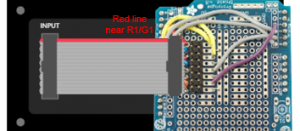
Step 1: Build the Adafruit protoshield
First, follow this Adafruit tutorial to build your own protoshield and connect the Bluno board to the RGB Led matrix.
You can download the PDF version of the Adafruit tutorial.
RGB LED matrix and Bluno pins :
| RGB LED matrix | Bluno |
|---|---|
| R1 | D2 |
| B1 | D4 |
| R2 | D5 |
| B2 | D7 |
| A | A0 |
| C | A2 |
| CLK | D8 |
| OE | D9 |
| G1 | D3 |
| GND | GND |
| G2 | D6 |
| GND | GND |
| B | A1 |
| D | GND (?) |
| LAT | A3 |
| GND | GND |
Check your protoshield and the ribbon cable connection very carefully.
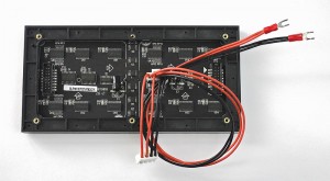
Then, connect a power source to the Adafruit RGB Led matrix and connect the Bluno to your computer.
You can test your screen by executing one of these RGB matrix panel library 16×32 examples.
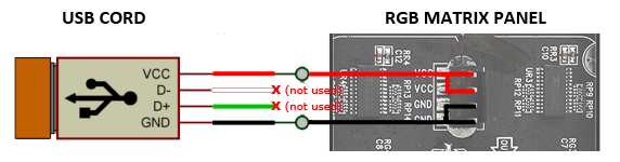
Step 2: Build the USB power cord
Now, let’s make a specific USB power cord to connect the RGB matrix panel to the Xiaomi battery.
For this, you need the original Adafruit power cord:
And a USB cord:
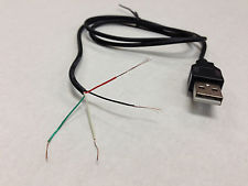
To connect the USB cord to the Adafruit power cord, you need to connect the matching 5V and Ground pins of each cord together:
Step 3: Add temperature sensor and realtime clock to the protoshield
Now you need to add the temperature sensor and the real time clock to your Protoshield:
Temperature sensor pins:
| Temperature sensor | Bluno |
|---|---|
| Left ( – ) | GND |
| Middle | 5V |
| Right ( S ) | D12 |
Real time clock pins:
| Real time clock | Bluno |
|---|---|
| SCL | A4 |
| SDA | A5 |
| VCC | 5V |
| GND | GND |
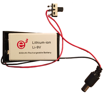
Step 4: Build a power supply
Create a power supply with a switch button:
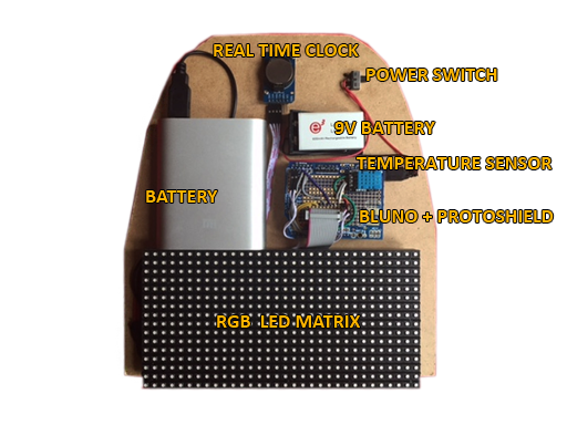
Step 5: Assemble the main board
Now you are ready for the final assembly. Begin with the LED matrix installation.
Important: make sure you position your LED matrix correctly on your mainboard so that it matches your backpack’s “viewing window”.
Then fix all the electronic components you have prepared on the main board:
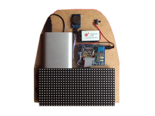
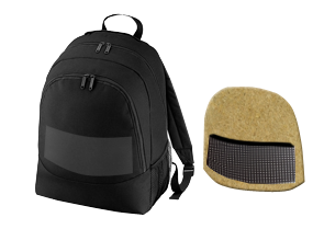
Now you can install your main board in your bag.
Ok the backpack hardware is ready, so let’s build your Arduibag remote control !